Aerodynamics: Technical Discussions
Minimizing Vehicle Drag—A New Method
The long-sought quest to enhance the aerodynamics of open-wheeled vehicles is a surprisingly complex topic, being a system mechanical problem of how the rotating wheel actually affects overall vehicle drag. Our present investigation has led to numerous drag-reducing inventions that overturn common industry vehicle drag models, and therefore invite considerable skepticism. For that reason, we endeavor herein to more fully explain the technical nature of this new approach to minimizing vehicle drag and maximizing vehicle traction and stability.
We target our explanation below for those having substantial technical competence in systems mechanical engineering, hoping that they then will begin to appreciate the in-depth arguments discussed below. However, for others simply needing an overview of this new technology, please see our summary arguments above.
Vehicle Drag Highly Concentrated on Uppermost Wheel Surfaces
We start our expanded discussion then with a platform that lends itself well to exploring vehicle efficiency: the bicycle, being quite sensitive to drag, and having very limited propulsive power actually available in pedaling against headwinds. As a result, cycling enthusiasts—and industry efforts—are pushed to counting individual watts saved in order determine incremental improvements in vehicle propulsive efficiency. However, counting single watts under changing wind conditions is a largely impossible challenge, as only slight changes in wind conditions between individual tests can overwhelm the minor changes needed to be measured.
This measuring challenge has caused industry to conduct measurements within wind tunnels, where headwinds can be accurately controlled. However, wind tunnel measurements also presents complications, since typical measurements of vehicle drag forces have been generally conducted thus far as if open-wheeled vehicles were airplanes, where all surfaces are exposed to the same wind speed.
This preference for interpreting how drag forces on the vehicle affect vehicle efficiency has been also true in conducting automotive measurements, where drag forces against the frame are measured, being an inaccurate means to actually determine overall vehicle efficiency. Simply spinning the wheel does not capture the actual vehicle efficiency, since the axle is commonly tied to the floor, changing the vehicle drag mechanics away from a real world road condition.
And our recent patent US 9,766,153, teaches a more effective method for measuring vehicle efficiency inside a wind tunnel, where the vehicle is self-propelled while unrestrained—as it is on the road—while actual power dissipated in drag is instead directly measured, eliminating any interpretation errors in measuring drag forces.
Shielding Nearly Eliminates Critical Upper Wheel Drag on Open-Wheeled Vehicles.
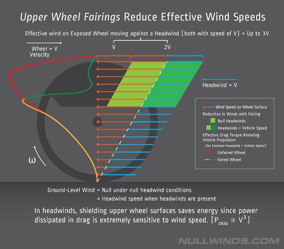
Clearly, the wheel itself is exposed to highly variable wind speeds, which then affects propulsive vehicle efficiency in differing magnifications, depending on where the individual wind components actually impinge upon a surface of the wheel. At the top of the wheel, wind speed is at least twice the vehicle speed. And the bottom of the wheel is actually stationary where contacting the ground, and thus exposed to no wind. (Only the outline of the wheel is moving at the vehicle speed; wheel surfaces inducing frictional drag are highly variable in exposed wind speeds as the wheel rotates.)
Moreover, our original patent US 9,878,745 is the first to teach that actual vehicle drag produced by the wheel is highly magnified near the top of the wheel, and highly de-magnified near the bottom of the wheel. For this reason, the top of the wheel should be optimized for minimal drag, whereas drag on the bottom of the wheel can be largely ignored, and which is best left exposed to any wind.
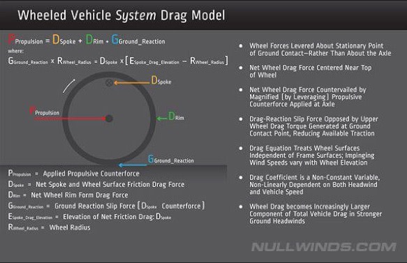
Indeed, due to leveraging, lower wheel surfaces are more easily pushed at the axle against headwinds than any frame surface. For this reason a wheel rolls easily over uneven road surfaces; the wheel having a clear propulsive advantage over resistive forces applied thereto below the axle. (Try comparing lower wheel surface resistance against upper wheel resistance using a toy car.)
Thus, current industry efforts to optimize bicycle wheel rim shape for minimal drag at the level of the axle are misguided. The rim should be optimized for minimal profile drag from crosswinds at the level of the axle, but need not be optimized thereto for minimal headwind drag, since at the level of the axle the wheel actually imparts considerably less than commonly assumed to overall vehicle drag.
Optimal Bicycle Aero Wheel Design
With these design considerations in mind, it becomes clear that an optimal bicycle wheel design will minimize drag near the top of the wheel, while also allowing for maximum crosswind transparency. In order to achieve crosswind transparency, however, rim depth should be minimized. But deeper rims have been utilized in recent aero wheels in order to minimize spoke length exposed to winds, in spite of increased crosswind instability induced on the bicycle—which decreases both safety and pedaling efficiency.
More expensive aero wheels are often designed both with minimal spoke count and reduced spoke length, even though substantial rim surface area is added to the wheel to order to achieve this minimal exposed spoke surface condition. In spite of the vastly increased rim surface area exposed to winds, these deep rim wheels are proven effective due to the reduction of substantial vehicle drag otherwise induced by the outermost spokes located near the more shallow wheel rim.
And it turns out that the most effective aero wheels—and also the most expensive—also have hidden nipples, making these high-end wheels harder to maintain and service. Indeed, the larger nipple surface is also exposed to the fastest wind speed at the top of the wheel—where wheel drag is most magnified against propulsive counterforces directed at the axle—thereby greatly exacerbating the power being dissipated in drag thereon.
Indeed, spoke drag is far more critical to inducing overall vehicle drag than is commonly understood, especially in the presence of any crosswind, being a non-obvious greater effect on vehicle propulsive efficiency. And with the recent introduction of bladed aero spokes, reduced headwind drag is obtained under null crosswind conditions, being thereby very effective inside the wind tunnel where the measured wheel is often exposed only to headwinds. However, cyclists know that in any windy condition, a substantial crosswind component is also present most of the time while cycling.
Still, bladed spokes have largely replaced traditional round spokes in more expensive aero wheels, being a trend largely aimed at selling replacement wheels. But any substantial crosswind across the flat blade of the spoke quickly turns any laminar flow condition thereon to turbulent, immediately increasing drag induced on the spoke by a factor of two or more, and—critically—increasing the power being dissipated by the spoke by at least eight times higher.
This vastly increased power dissipation on the spoke greatly diminishes vehicle propulsive efficiency, especially at higher wind speeds. For this reason alone, bladed spokes should not be used in windy conditions, the very conditions when many—if not most—cyclists ride.
But since headwind drag is the most dominate consideration when measuring wheel drag inside a wind tunnel, aero wheels have largely gained acceptance, despite being both slower and more unstable in crosswinds. Only recently has crosswind effects in the design of aero wheels gained substantial consideration within industry, and especially since the introduction of our patented solution, SPOKE FINS™ in US 9,290,041, which is aimed specifically at providing optimally reduced drag even under crosswind conditions.
Previous Section - Next Section